


Connectable cable cross-section by current rating
The table below shows the smallest and largest conductor cross-section that fits the terminals of Bemis CEE products. The values are the same as the Connectable Cable Cross-Section row on each product page and datasheet.
| Current | Plug, connector, appliance inlet, wall inlet | Wall-mounted socket, panel-mounted socket |
|---|---|---|
| 16 A | 1 – 2.5 mm² | 1.5 – 4 mm² |
| 32 A | 2.5 – 6 mm² | 2.5 – 10 mm² |
| 63 A | 6 – 16 mm² | 6 – 25 mm² |
| 125 A | 16 – 50 mm² | 25 – 70 mm² |
| 250 A | 70 – 150 mm² | 70 – 185 mm² |
On 24 V extra-low-voltage products (16 A and 32 A) the terminal range is 4 – 10 mm². To browse products by current rating, see the guide on choosing by current rating.
Why do plugs and sockets have different terminal ranges?
Plugs, connectors and appliance inlets are mostly used with stranded flexible cable; the cable enters through the gland at the back of the housing, and the outer diameter the gland can clamp is limited. Wall and panel sockets are connected to the fixed installation; as the run gets longer, a thicker cable may be laid to limit voltage drop, so their terminals also accept the next cross-section up. This is why, at the same current rating, the upper limit of a socket is higher than that of a plug.
How to choose the cable cross-section
The terminal range only tells you whether a cable can be connected to the product; the installation determines which cross-section should be used. Four factors are considered together:
- Load current and protective device: The current-carrying capacity of the cable must not be lower than the rated current of the fuse or circuit breaker protecting the circuit.
- Cable length: On long runs, voltage drop becomes the deciding factor.
- Installation method and ambient temperature: A cable laid in conduit, in a bundle or in a hot environment carries less current.
- Cable type: For mobile use, a flexible cable resistant to external influences (e.g. H07RN-F) is preferred.
Under normal conditions and on short runs, common practice for copper cables is 2.5 mm² at 16 A, 6 mm² at 32 A, 16 mm² at 63 A and 35–50 mm² at 125 A; all of these fall within the terminal ranges above. The exact cross-section must be calculated by the qualified electrical engineer responsible for the project, in line with the wiring regulations (IEC 60364-5-52).
Voltage drop calculation
On a copper line, voltage drop is approximately ΔU = √3 × I × L × cos φ / (56 × S) in a three-phase system and ΔU = 2 × I × L × cos φ / (56 × S) in a single-phase system, where I is the current (A), L the cable length (m), S the conductor cross-section (mm²) and 56 the conductivity of copper.
Example: in a 400 V three-phase system, a load drawing 32 A at a distance of 50 m on a 6 mm² cable gives ΔU ≈ 1.732 × 32 × 50 / (56 × 6) ≈ 8.2 V, i.e. about 2% (assuming cos φ = 1). If the same run were 100 m, the drop would double and a 10 mm² cable might be required; this is why 32 A wall and panel sockets accept cable up to 10 mm².
Number of cores
The number of cores in the cable must match the number of poles of the plug and socket: 3-core cable for 3P (2P+E), 4-core for 4P (3P+E) and 5-core for 5P (3P+N+E) products. How to read the number of poles is explained in the guide on pole count and clock position.
Cable cross-section and length on cable reels
On a cable reel, the larger the cross-section, the larger the outer diameter of the cable and the shorter the length that fits on the drum. For example, the longest cable that can be wound on Bemis cable reels with the BM4 drum is as follows (based on the outer diameter of H05VV-F cable):
| Cores | 1.5 mm² | 2.5 mm² | 4 mm² | 6 mm² |
|---|---|---|---|---|
| 3-core | 80 m | 60 m | 40 m | 35 m |
| 4-core | 70 m | 45 m | 40 m | 25 m |
| 5-core | 60 m | 40 m | 25 m | 20 m |
Each reel model has its own cable capacity table on its product page. Because wound cable cannot dissipate heat, the cable must be fully unwound when the reel is used at high current.
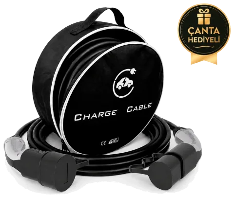
Cross-section of EV charging cables
Besides the power conductors, charging cables contain a thin pilot conductor that carries the communication between the vehicle and the charger. The cross-sections used in Bemis E-V Charge charging cables and charging sets are:
| Charging power | Current | Cable construction |
|---|---|---|
| 3.7 kW single-phase | 16 A | 3 × 2.5 mm² + 1 × 0.75 mm² |
| 7.4 kW single-phase | 32 A | 3 × 6 mm² + 1 × 0.75 mm² |
| 11 kW three-phase | 16 A | 5 × 2.5 mm² + 1 × 0.75 mm² |
| 22 kW three-phase | 32 A | 5 × 6 mm² + 1 × 0.75 mm² |
For the differences between AC and DC charging, see the guide on EV charging types.


 15 m
15 m  50 m
50 m  40 m
40 m  100 m
100 m  16 A
16 A  32 A
32 A  63 A
63 A  125 A
125 A  11 kW
11 kW  22 kW
22 kW  Type 2
  CCS2
CCS2